

WEATHER INFORMATION
Content:
Aviation Weather Reports (METAR)
Temperature, Dew Point, Altimeter Setting Pressure
Special Weather Reports (SPECI)
Automatic Weather Station Reporting Systems (AWOS)
GFA Weather Information—CLDS & WX GFA
Dynamic Systems
GFA Weather Information— ICG/TURBC/FRLVL
Severe Icing and Turbulence Inserts
GFA Amendments and Corrections
Change Groups: From, Becoming, Temporary, and Probability
PIREPs, AIRMETs, SIGMETs, and RADAR REPORTS
Getting a Pilot Weather Briefing
Aviation Weather Reports (METAR)
The METAR (Aviation Routine Weather Report) is the most common weather reports used by pilots. The following is a typical example of the METAR format:
METAR CYYC 071500Z 04010KT 11/2SM -RAFGFU FEW003 OVC007 05/04 A2983 RMK SF2 ST6 VIS 1 SW SLP 115
A METAR is a description of weather conditions at a particular place and particular time. They are prepared hourly, or whenever there is a significant weather change, by Environment Canada or Flight Service personnel at specified airports (listed in the Aeronautical Information Publication). Let us now look at interpreting the code.
Type of Report
METAR CYYC 071500Z 04010KT 11/2SM -RAFGFU FEW003 OVC007 05/04 A2983 RMK SF2 ST6 VIS 1 SW SLP 115
Although METARs are most commonly used, there are actually three categories of aviation weather reports: METAR, SPECI, and METAR CCA.
The header “METAR” indicates a regular observation, completed hourly.
With a significant change in weather, a “SPECI” will be released anytime (see below).
If a METAR requires a correction the expression “CCA” indicates the first correction (“CCB” indicates the second correction, if necessary), and this notation appears behind the date and time of observation.
Station identification
METAR CYYC 071500Z 04010KT 11/2SM -RAFGFU FEW003 OVC007 05/04 A2983 RMK SF2 ST6 VIS 1 SW SLP 115
In METARs, the identification—e.g., CYYC indicating Calgary International Airport—always consists of four letters.
The first letter “C” indicates Canadian, while the second letter designates the type of weather reporting station:
Y or Z reporting station co-located with an airport
W reporting station not co-located with an airport
U reporting station co-located with a radio beacon
The last two letters identify the airport—e.g., VR (Vancouver), YC (Calgary), EG (Edmonton), or WG (Winnipeg). Airport identifications are published in the Canadian Flight Supplement.
Date and Time of Issue
METAR CYYC 071500Z 04010KT 11/2SM -RAFGFU FEW003 OVC007 05/04 A2983 RMK SF2 ST6 VIS 1 SW SLP 115
This is rather straight forward, and incidentally a common date/time format used in aviation information: this METAR was issued on the 7th day of the month (month not specified), at 1500Z.
Wind
METAR CYYC 071500Z 04010KT 11/2SM -RAFGFU FEW003 OVC007 05/04 A2983 RMK SF2 ST6 VIS 1 SW SLP 115
Winds are reported with the first three numbers indicating the direction (rounded to the nearest 10°), while the last two numbers indicate speed; therefore, in this example the winds are 040° at 10 KTS.
Calm winds are indicated by “00000KT.” Gusty winds are indicated by “G”—24015G20KT—where the winds are 15 KTS gusting to 20 KTS. Where the winds are light variable, the abbreviation VRB appears—220VRB. If variable winds during the ten minutes before the observation varied more than 60° and the mean (average) speed exceeded 3 KTS, the wind is reported as follows: 030V140.
Importantly, the wind direction is indicated in degrees TRUE, not magnetic (remember, the only time wind direction is given as magnetic is when provided by the tower during landings and takeoffs). Wind speed is always in KTS.
Prevailing Visibility
METAR CYYC 071500Z 04010KT 11/2SM -RAFGFU FEW003 OVC007 05/04 A2983 RMK SF2 ST6 VIS 1 SW SLP 115
Importantly, visibility is always given in statute miles (not nautical) and it appears after wind information. In this case the winds are 1 ½ statute miles.
Runway Visual Range
METAR CYYC 071500Z 04010KT 1SM RW34/5000FT/D -RAFGFU FEW003 OVC007 05/04 A2983 RMK SF2 ST6 VIS 1 SW SLP 115
This feature of the METAR has been inserted for demonstration purpose only (note the reduction in visibility to 1 SM—in VFR weather, Runway Visual Range will not appear).
Runway Visual Range (RVR) is used for IFR operations and therefore is not important for VFR pilots—RVR is typically only used when the prevailing visibility is well below VFR limits.
It represents the visibility along the touchdown points of selected runways, and is reported in feet when the visibility is 1 mile or less.
Present Weather
METAR CYYC 071500Z 04010KT 11/2SM -RAFGFU FEW003 OVC007 05/04 A2983 RMK SF2 ST6 VIS 1 SW SLP 115
This is an important section and you want to be familiar with the format and codes used here; in this example they are calling the weather light rain, with fog and smoke.
This section describes any weather phenomena existent at the airport, specifically noting precipitation, sky obscuration, or any other weather phenomena.
Qualifiers
“Qualifiers” precede the weather phenomena description which denotes the intensity or proximity of the phenomena.
With respect to intensity, the references used are light—indicated by a minus sign (-), moderate—where a sign is not used ( ), and heavy—indicated by a plus sign (+).
With respect to proximity, the only reference used is VC, which stands for in the vicinity.
If the intensity of reported phenomena is light or heavy, the appropriate sign is used; if the intensity is moderate, or when the intensity is not relevant to the phenomena (e.g., volcanic ash or a funnel cloud), no sign is included.
Where more than one precipitation phenomena is reported, the predominant type of precipitation is reported first, but the intensity grade only represents the “overall” intensity of the combined precipitation types.
The code “VC” (in the vicinity) is used if the phenomena are located within 5 miles of the airport, but not at the airport itself.
Descriptors
In contrast to the qualifiers (which really are, for the most part, intensity), the “descriptors” describe the form the weather is taking. The associated codes must be memorized:

Weather Phenomena
Now we get to the bones of the METAR that really is the weather at hand, and these too will have to be memorized:

The descriptors of “MI” (shallow), “BC” (patches) and “PR” (partial) are used only in combination with fog (“FG”)— e.g., “BCFG.” Similarly, “DR” (drifting) and “BL” (blowing) are only used in association with “SN” (snow), “SA” (sand), or “DU” (dust).
If “BLSN” (blowing snow) and “SN” (snow) occur simultaneously, they are both reported, but in distinct present weather groups—e.g., “SN BLSN.”
The code “SH” (showers) is only used in association with precipitation types—i.e., “RA” (rain), “SN” (snow), “PL” (ice pellets), “GR” (hail), and “GS” (snow pellets) if they occur at the time the observation is made—e.g., “SHSNGS”
The code “TS” (thunderstorm) is reported alone or in combination with one or more precipitation types. The thunderstorm is considered to have ended if thunder has not been heard within the last 15 minutes. Note that “TS” and “SH” cannot appear together since present weather groups can only have one descriptor.
Finally, note that “FZ” (freezing) can only be used in association with a precipitation type— “DZ” (drizzle), “RA” (rain), and “FG” (fog).
Where the reported weather phenomena is precipitation of different kinds, these are combined to form one group; the only exception to this is “FZ” (freezing precipitation) which is always reported as a separate present weather group (e.g., FZRA or FZDZ).
Any obstructions to vision (obscuration) are reported when the prevailing visibility is 6 SM or less. If the obscuration occurs simultaneously with one or more types of precipitation, the obscuration type is reported as a separate present weather group. Note that both BR and FG refer to fog; BR is used when the visibility is greater or equal to 5/8 SM., while FG is used when visibility is less than 5/8 SM.
“Other phenomena” are reported in separate groups, and codes for funnel clouds, tornadoes or waterspouts are repeated in the remarks section where they are written out if full (e.g., RMK TORNADOS).
Sky Opacity
METAR CYYC 071500Z 04010KT 11/2SM -RAFGFU FEW003 OVC007 05/04 A2983 RMK SF2 ST6 VIS 1 SW SLP 115
This group describes the sky condition with respect to cloud layers aloft. Heights are reported in hundreds of feet, and cloud opacity (i.e., the amount of visible sky observed through a layer) is reported in eighths (e.g., 2/8), known as “oktas”; for example:

Note that the cloud opacity reported is in fact a “summation amount” for the cloud layers observed from the surface. Accordingly, if two scattered layers are observed, each composed of 3/8th cloud, the second layer actually described as “broken” (3/8+3/8=6/8).
If the sky is obscured by a ground-based phenomenon—i.e., fog or mist— “vertical visibility” is reported instead of cloud opacity, indicated by the code “VV.” The VV code is followed by a three-figure value that represents vertical visibility in hundreds of feet.
Note: -BKN (thin broken) and ‑OVC (thin overcast) do not constitute ceilings for the purpose of restricting VFR flight. Instead, a “cloud ceiling” is said to exist at the height at which the first layer is described as “BKN” or “OVC.”
Where significant convective clouds exist—i.e., a cumulonimbus or towering cumulus—these are identified by the codes CB or TCU, and are attached to the cloud group without a space (e.g., SCT025TCU).
Temperature, Dew Point, Altimeter Setting Pressure
METAR CYYC 071500Z 04010KT 11/2SM -RAFGFU FEW003 OVC007 05/04 A2983 RMK SF2 ST6 VIS 1 SW SLP 115
Temperature and dew point are rounded off to the nearest whole number, and negative temperatures are proceeded by the letter M.
A2992 equals 29.92 “Hg.
Wind Shear
There is no wind shear in this example; nevertheless, it will appear when a wind shear is reported within 1600’ AGL on the departure or approach end of runways, the runway numbers will be identified following the indicator WS.
Remarks
METAR CYYC 071500Z 04010KT 11/2SM -RAFGFU FEW003 OVC007 05/04 A2983 RMK SF2 ST6 VIS 1 SW SLP 115
Remarks will appear at the end of the sequence, prefaced by RMK. The remarks will, where observed, contain the cloud layer type and degree of opacity of sky covered by the layers in eighths, or “oktas,” each layer described corresponding to the sequence contained in the “sky condition” depicted earlier in the report.
For Example:
CI7 is interpreted as Cirrus covering 7/8 of the sky
NS2 is interpreted as Nimbostratus covering 2/8 of the sky
SF6 is interpreted as Strato fractus covering 6/8 of the sky
CB4 is interpreted as Cumulonimbus covering 4/8 of the sky
Additional cloud types are abbreviated as follows: CS - cirrostratus; CC - cirrocumulus; AS - altostratus; AC - altocumulus; ST - stratus; SC - stratocumulus; ACC - altocumulus castellanus; CU - cumulus; CF - cumulus fractus; TCU - towering cumulus; and CI – cirrus.
Sea Level Pressure, reported in hectopascals (hPa) is reported at the end of the data, behind letters SLP. It may be noted that the initial “9” or “10” is omitted because sea level pressure varies only between 960.0 milibars and 1050.0 hPa (this need not be memorized). For example:
263 represents 1026.3 hPa
983 represents 998.3 hPa
Special Weather Reports (SPECI)
SPECI appear for reporting stations whenever there is a significant change in the weather that occurs between scheduled hourly transmissions. In particular, a SPECI will be issued if any of the following occur:
-
the ceiling decreases to 1500’ or less, or when a cloud layer, previously not reported, appears below 1000’ (or below the highest minimum for straight-in IFR landings, or the minimum for IFR departures);
-
visibility decreases to below 3 SM.;
-
a tornado, waterspout or funnel cloud is reported;
-
a thunderstorm begins, intensifies to “heavy,” or ends;
-
precipitation begins, changes, or ends;
-
winds suddenly increase and exceed 30 KTS (speed must double), or when the direction of the winds significantly changes (satisfying the criteria for “wind shift” (see “wind” above).
Automatic Weather Station Reporting Systems (AWOS)
There are three types of automatic weather station reporting systems, identified as AWOS 1, 2, and 3. AWOS 1 reports wind, altimeter setting, temperature, and dew point. AWOS 2 has visibility, and AWOS 3 has cloud layers.
Formats for AWOS reports are somewhat different from that of SA reports, and for this reason, FSS should be consulted for interpretation (see Aeronautical Information Publication MET 3.15.2).
Graphic Area Forecasts (GFA)
GFAs provide a graphic depiction of the most probable weather conditions over a specified region at a specific time. The regions, referred to as “domains” are depicted below.

Information provided on GFAs pertains only to weather conditions below FL240 (24000’ ASL).
GFAs are issued every six hours, with the validity period of each issue beginning at the “top” and “bottom” of the Zulu (UTC) clock—0000Z, 0600Z, 1200Z, and 1800Z.
Since they are issued ½ hour before the validity time, newly published GFAs are available for use at 1130Z, 0530Z, 1130Z, and 1730Z.
Each issue of the GFA, in fact, consists of six charts, and the six charts, in turn, consist of three pairs, with each pair made up of one Clouds and Weather—abbreviated as CLDS & WX—and one Icing, Turbulence, and Freezing Level chart—abbreviated as ICG/TURBC/FRLVL.
The three paired charts that made up a GFA issue become valid—i.e., represent an accurate picture of the forecasted weather conditions—at three different times following the time of issue. The first pair provide a near-term forecast, and for this reason, this pair is referred to as the—you guessed it—the “Near-term Forecast.” If, for example, the GFA was issued at 2330Z, this first pair—the Near-term Forecast—would depict the expected weather at 2400Z. The second pair of charts—referred to as the Six-hour Forecast will in turn depict the weather conditions expected to exist 6-hours into the forecast period—in this case, for example, they will show the conditions expected at 0600Z—to be valid six hours after the start of the GFA issue valid time. The third and final pair of charts—referred to as the Twelve-hour Forecast—will then depict the weather conditions expected to exist 12-hours into the forecast period—in the case we have been using, for example, (with a GFA issued at 2330Z and first becoming valid at 2400Z), this final pair will depict the weather expected at 1200Z.
A final note on the Twelve-hour Forecast charts is that they contain what is referred to as an “IFR outlook” section, which summarizes conditions expected during the subsequent 12 hours following the validity start-time of the Twelve-hour Forecasts charts—in this case from 1200Z to 2400Z.
So you can see that the trick in using GFAs is sorting out the validity times of three paired charts that make up an issue. Perhaps the layout below may help in visualizing GFA organization.

It is interesting to note here that, at any of the six-hour blocks, there will be three different sets of GFA that provide what appears as a valid forecast for the time indicated—essentially the top and bottom of the Zulu Clock (0000Z, 0600Z, 1200Z, etc.); however, only the latest issue is, of course, the more accurate forecast, and a pilot should make an effort to get this latest issue for flight-planning purposes.
General GFA Format
Each of the six GFA charts has the same format—the Weather Information Section (the graphic depiction itself), a Title Box, a Legend Box, and a Comments Box:

The title box indicates the issuing weather office, the GFA region for which the chart applies, the type of GFA chart (whether CLDS & WX or ICG/TURBC/FRLVL), the date and time of issue, and the validity date and time of the chart. Being able to identify the validity time of GFA, as we have said, is critical, so you want to be sure you get the reading of information in this box correct—separate the time and date of issue, on the one hand, from the time and date of validity, on the other hand. Once the validity time is sorted out, you can determine whether the GFA is Near-term, the Six-hour, or the Twelve-hour Forecast.
The legend box includes the basic weather symbols used, but also provides a scale bar depicting nautical miles—this scale bar used in determining the relative position of weather systems after the valid time.[1]
The comments box provides information that the weather forecaster considers important for the reader—e.g., the formation or dissipation of fog, increasing or decreasing visibility, etc. As well, standard phrases—typically of a cautionary nature— will appear in this box—“HGTS ASL UNLESS NOTED” and “TCU, ACC AND CB IMPLY SIG TURBC AND ICG. CB IMPLIES LLWS.” The most important feature of the comment box, however, are the “elaboration” that appears here—there are often weather systems that are so complex that those who draft the GFAs cannot fit all of the information into the little spaces that appear on the charts. Instead of trying to cram all of the written descriptions onto the map, they will simply assign a capital letter reference on the chart in the applicable location—the letter “A,” for example—and then provide the information under a matching letter “A” in the comment box. Finally, with respect to the comment box, it is here were the “IFR Outlook” found on Twelve-hour Forecast GFAs will appear.
[1] It is important to understand here that the GFAs provide what is essentially a “snap-shot” of the weather as it is positioned at the valid time indicated on each chart, but weather systems, of course, are always in a state of change—they are “dynamic.” As you will see the “snap-shot” also includes the crucial direction and speed of the system feature—a cold front, for example. If you want to know the position of the cold front and its associated weather three hours after the validity time, what most do is pencil in on the chart the advanced position in accordance the direction and speed indicated—a cold front travelling eastward at 20 KTS will, after the passage of three hours, be 60 miles further east. For Commercial Pilot students, it is this ability to plot a dynamic weather system that is tested on the Transport Canada written examination.
Examples of these three boxes appear below:
.jpg)
The “IFR outlook” portion provides an extended forecast view of conditions that can be expected 12-hours after the 12-hour GFA chart. The information here is very general in nature and simply indicates those areas where IFR weather is expected, the cause of the IFR weather, and any additional weather hazards that may be associated. There are three meaningful expressions that may be used here—IFR, Marginal VFR (MVFR), and VFR—and it is important to know the criteria associated with these expressions:

The following is a list of the codes that can appear in the GFA Comment Boxes:

GFA Weather Information—CLDS & WX GFA
The Weather Information portion of a GFA has two formats, one that is applicable to the Clouds and Weather (CLDS & WX), and the other applicable to the Icing, Turbulence and Freezing Level (ICG/TURBC/FRLVL). This section first examines the Clouds and Weather (CLDS & WX) GFA.
The CLDS & WX GFA provides a forecast of cloud layers and/or surface-based phenomena, visibility, weather and obstruction to vision that are expected at the valid time of individual charts. On the charts are found isobar lines that join areas of equal pressure, and also found are graphic depiction of any significant weather systems—referred to as synoptic features—that affect the weather. Typically, the synoptic feature will consist of the prevailing pressure patterns and the associated frontal systems. In the depiction on the right, for example, we are shown a low pressure centre with its location represented by the “x” in a circle. The low pressure below (AIM, MET 4.10) is shown to move easterly at 15 KTS, while the associated cold front (“icicles on a string”) is shown to move southeasterly at 10 KTS. If the speed of the system is less than 5 KTS, the letters “QS” will appear.

Clearly, the ability to decipher the symbols used in weather charts is important, and while the symbols may initially appear to you as hieroglyphs, they will with experience become rather straightforward. Below, then, are the symbols and meanings that can be expected on a GFA:

Clouds
The depiction of clouds on a CLDS & WX GFA represents the bases and tops of clouds that are expected between the surface and FL240 (24000’ ASL).
If the clouds are convective in nature—i.e., clouds that are formed as a result of being heated through contact with the earth’s surface, producing rising columns (TCU, ACC or CB)—then the tops of these will be indicated even if they extend over FL240.[1]
[1] Just a reminder that the higher the tops, the greater the severity of the weather produced by convective clouds.

Generally, the cloud type will be shown on a GFA if this is considered to be significant.
Note that if the cloud structure is organized,[1] the cloud depicted will be surrounded by a scalloped border indicating the general position of the structure.
Where clouds are expected, but the clouds lack any organization, then the scalloped border will not appear. Importantly, however, the scalloped border will appear where, even though cloud structure is lacking, the visibility is expected to be 6 SM or less.
Note that in the case of multiple-layered clouds, the amount of cloud—e.g., FEW, SCT or BKN—is not cumulative (as is the case with METARS, for example).
The term “LYRS” indicates that random clouds exist in a layer less than 1000’ thick, but does not constitute a solid cloud mass.
When a cloud layer is surface based—fog or mist, for example—the expression OBSCD (obscured) is used. Here they will provide vertical visibility: OBSCD CIG 3-5 AGL (the ceiling is obscured, but the vertical visibility is 300’-500’ AGL.
Generally, all heights are indicated in hundreds of feet ASL. Where heights are indicated above ground, the standard expression AGL will be used.
[1] “Organized,” means forming a distinct pattern.
Weather and Visibility
Visibilities are always reported in statute miles, and when visibilities are expected to be greater than 6 SM, the code P6SM is used.
If the visibilities are forecast to be 6 SM or less, the obstruction limiting the visibilities is described—e.g., 4SM –SHRA. The codes used here will be standardized in accordance with those that appear in METARs.
Areas where precipitation is forecast will be enclosed, in the case of intermittent or showery precipitation, by a dashed green line surrounding a hatched area, and in the case of continuous precipitation, by a solid green line surrounding a dotted (stippled) area.
Freezing precipitation (freezing drizzle or rain) is shown in red.
In an area where an obstruction to vision is not associated with precipitation, and where the visibility is nevertheless 6 SM or less, the area will be bounded by a dashed orange line.

For convective clouds and showers, the following additional abbreviations are used to denote density of the phenomenon:

For non-convective clouds and precipitation, low ceilings, precipitation ceilings, icing, turbulence, or restrictions to visibilities, the following additional abbreviations are used to denote density:

Winds and Pressure

Surface winds are placed on the GFA where the speeds are at least 20 KTS, and are indicated graphically by the wind barb and the associated speed values. A wind barb should be interpreted to show wind direction like an arrow, with the “tail feathers” indicating speed. A long tail feather represents a 10-KT value, while a short tail feather indicates a 5-KT value. The appearance of a triangle on the barb indicates 50 KTS. The depiction above represents a westerly wind with gusts to 35 KTS.
Also seen on the CLDS & WX GFA are isobars, which are set at 4-millibar intervals.

Below is depiction of the CLDS & WX GFA layout:

The centre of the low pressure is located about 60 NM to the east-south-east of Red Deer, and associated with this is a trowal that extends from 30 miles south of Red Deer to beyond the US border just south of Swift Current, Saskatchewan. We can see that the low pressure is quasi-stationary, but that the trowal associated with it is migrating to the northeast at a speed of 10 KTS. The weather associated with the low pressure and trowal is surrounded by a scalloped border that extends up into central Alberta (circled with superimposed dashed lines), and indicates broken cloud layers based at 7000’ ASL, topped at 18000’ ASL, with frequent scattered ceilings based at 1500’ to 2500’ AGL, and that these lower ceilings are associated with precipitation. We are also advised that local stratus ceilings exist in this general area, and that these are as low as 400’ AGL. Also, we can expect scattered altocumulus castellanus clouds topped at 18000’ that will produce 4 SM visibility in light rain showers. In contrast, behind the trowal—in the triangle extending east from Lethbridge to include Medicine Hat—we can expect scattered altocumulus clouds; they will be based at 10000’ ASL, and topped at 14000’ ASL, giving visibilities greater than 6 SM. Comment “B” also specifies that the system will likely produce a few cumulonimbus clouds with tops as high as 24000’ ASL, but that these will likely not appear until after 2000Z; when they do appear, they will be associated with visibilities of 4 SM owing to light rain from thunderstorms. Finally, Comment “A” warns of locally low visibilities—as low as 1 SM—and ceiling—500’ AGL—in mountainous areas owing to snow showers.
Dynamic Systems
It is important to remember that the systems on the GFA are in fact continually in motion, moving in accordance with the speed and direction information provided on this chart. In the chart that appears on the preceding page, for example, the low centre is stationary, but the trowal is migrating to the northeast at a speed of 10 KTS. And, importantly, not only is the trowal migrating, but so is the weather associated with it.[1] If, for example, we are interested in the position of the weather 6 hours after the issue of the above chart, we can anticipate the position of the trowal to be some 60 NM to the north-east of its current position; similarly, the associated weather depicted ahead of the trowal, as well as the weather behind the trowal, will also move about 60 NM to the north-east. Make use of the Scale always drawn on the chart. Below is a depiction of the advanced trowal—6 hours after the issue of the original GFA. Note the evolving position of the two cloud mass boundaries:
[1] The exception to this, of course, would be the weather associated with mountainous areas (mountain waves, for example).
I'm a paragraph. Click here to add your own text and edit me. It's easy.
I'm a paragraph. Click here to add your own text and edit me. It's easy.

GFA Weather Information— ICG/TURBC/FRLVL
The ICG/TURBC/FRLVL GFA provides a forecast of areas of icing and turbulence, as well as the expected height of the freezing level at the specified time of the chart. Included in the depiction are the type, intensity, bases and tops of the expected icing and turbulence areas. The surface synoptic features that appear on the CLDS & WX GFAs also appear on the ICG/TURBC/FRLVL GFA.
Icing
Forecast areas of icing will only appear whenever moderate or severe icing is anticipated. The vertical feature of the icing conditions will be presented in a format identical to that with cloud. Note that areas of light icing will not be specified graphically on the chart, but instead will appear in the Comments Box. The following example depicts an area of moderate mixed icing, based at 2000’ ASL, topped at 13000’ ASL:

Should the icing conditions be expected during only a part of the forecast period for which the GFA is published, the time of occurrence of the icing will be indicated in the Comments Box.
Turbulence
Areas of turbulence will be depicted on the GFA whenever forecast to be moderate or severe in magnitude. In the event that the turbulence is the result of mechanical turbulence, low-level wind shear, mountain wave activity, or clear air turbulence, an abbreviation will appear indicating the cause. The depiction on the right shows moderate clear air turbulence between 8000’ASL and 20000’ ASL.

Overlaying areas of turbulence are indicated as follows (AIM Met 4.12):

The following interpretations with respect to the level and definition of turbulence are applied:

Severe Icing and Turbulence Inserts
Areas of severe icing or severe turbulence can be inserted in a wider area of moderate icing or turbulence as indicated below (AIM Met, 4.12):


Freezing Level Isotherms
The freezing level isotherms are indicated on the GFA as dashed lines. The height of the freezing levels is indicated as heights ASL, and is depicted in 2500’ intervals. Note that the air mass depicted here is therefore warmer as you proceed south—the freezing level rises. Special modifications of the freezing level—associated with, for example, warm air aloft—will be explained in the Comments Box.

Above Freezing Layers
Areas where above freezing precipitation is suspended above a cold air mass (typically associated, for example, with warm fronts in winter) are indicated as below (AIM Met 4.12) as indicated below:

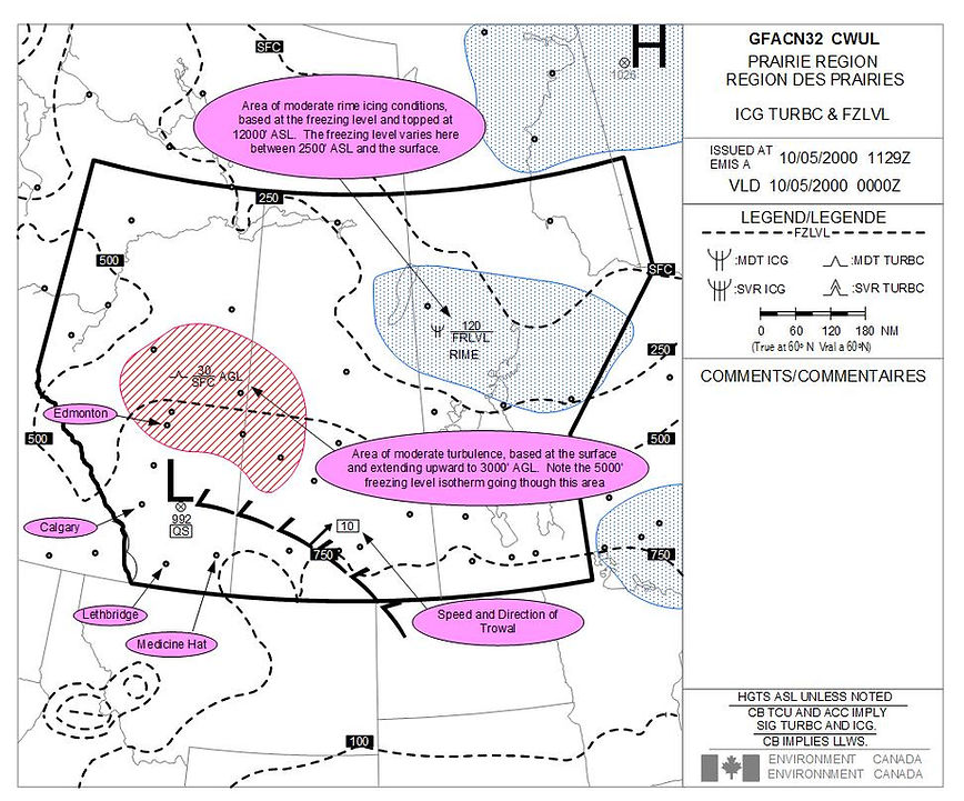
Below is a sample ICG/TURBC/FRLVL GFA. Note that the freezing level is at the surface in the upper right-hand area of the chart, and rises to 7500’ in southern Saskatchewan and Manitoba. The area of icing depicted in north-central Manitoba shows moderate rime icing, based at the freezing level (which is on the surface in the northern portions of the chart), and topped at 12000’. This area of icing may or may not move to the Northeast in conjunction with the movement of the trowal. We also note the area of moderate turbulence along the central Alberta-Saskatchewan border. The vertical dimensions are defined as extending from the surface to 3000’ AGL and the cause is mechanical disturbance of the airflow by the surface; because of the proximity of this area of turbulence to the low pressure—likely the cause—it will probably remain stationary and build or dissipate with the low pressure. Finally, note the standard cautions that appear in the lower portion of the Comment Box—all heights are above sea level unless otherwise advised, reference to CBs, TCUs, or ACCs imply significant turbulence and icing, and with reference to CBs also implies low-level wind shear.
Low-level Jets
Also reported on the Icing, Turbulence, and Freezing Level GFAs are Low-level Jets. They appear when the core speeds are 50 KTs or more, or in the case of significant turbulence or shear is expected, when the winds are between 35 and 45 KTs. Here is how they are depicted (AIM Met 4.12):


GFA Amendments and Corrections
GFAs are automatically amended by AIRMETs whenever conditions considered significant for aircraft have not been forecasted and do not, therefore, appear in the GFAs. The AIRMET will specify the GFA amended. Also, GFAs are automatically amended by SIGMETs, even though this will not be explicitly stated.
A GFA, in turn, will be re-issued where one or more of the original GFA charts contain a significant error that could lead to misinterpretation. Such corrective GFAs will indicate this by the code “CCA” which appears in the Title Box, with the “A” indicating the first correction—should a “CCB” appear, the “B” will indicate that the GFA issue is the second correction, etc.
Aerodrome Forecasts (TAF)
TAFs describe the weather conditions that will affect landings and takeoffs at specified aerodromes.
Importantly, heights of clouds are always reported above ground, and the area to which a TAF applies is limited to within 5 NM of the aerodrome.TAFs are issued usually one-half hour before the coverage period, and the coverage period can be 12 hours, 24 hours, and 30 hours; they are issued approximately 20 to 35 minutes in advance of their validity times, which appear at the top and bottom of the Zulu Clock The source airports and standard coverage periods for the three variations are indicated below (AIM, Met 7.1).

SPacer

Change Groups: From, Becoming, Temporary, and Probability
TEMPO means a “temporary change” in forecast conditions, in this case between 1800Z on the 29th day and 0100Z on the 29th day (indicated by 2918/2901), where the conditions will change to 1 and 1/2 SM visibility, owing to light snow and moderate blowing snow, accompanied by a broken layer based at 800’ AGL.
As a rule, whenever a “change group” is depicted, whether it appears as FM for “from,” BECMG for “becoming,” TEMPO for “temporary,” or PROB for “probability,” the specified weather elements described in the change group (whether it be precipitation, visibility, or cloud layers) replace the equivalent weather elements that existed previously to the change. For example, “FEW030 BKN050 OVC080 . . . [change group type] . . . BKN050” implies that the three cloud layers predicted prior to the change will no longer exist, with only the one broken layer existing at 5000’.
Here are the criteria associated with the different change group types:
FM220130Z
FM appears whenever a permanent change to the forecast weather is expected to occur rapidly.
All forecast conditions that previously occurred are replaced or superseded. Accordingly, all forecast weather elements will appear after this code, including the conditions unaffected by the change. The time at which the rapid change is forecast to occur is also depicted, in this case 0130Z on the 22nd day (day, hours and minutes). There is a slight complication with the FM code: if there are additional changes within the hour following the time depicted, those additional changes make reference using “whole hours.” This is best explained by an example: let us assume that “FM280915Z” appears; if there was a subsequent temporary change, say forecast to begin shortly after 0915Z on the 28th day, those changes would be depicted as “TEMPO 2809/2811” (lasting from 09Z on the 28th day to 11Z on the 28th day), when in actuality they are expected between 0915Z and 1100Z on the 28th day.
BECMG 2206/2208
This indicates a permanent but gradual change in conditions expected to evolve over a period of time (normally one to two hours, but never more than four hours)—in this case from 0600Z on the 22nd day to 0800Z on the 22nd day.
Any weather element that is not indicated as part of the BECMG conditions remains the same as depicted in the period preceding. If the change entails significant weather, however, all of the weather-associated elements will be included even though they are unchanged; the code NSW is used when significant weather is forecast to end. The use of this change group is kept to a minimum (owing to its complexity, thank goodness!), and is only used in those cases where only one or two weather groups are expected to change while all others remain the same; when more than two weather groups are forecast to change, the depiction “FM” will be used to start a new self-contained weather sequence.
TEMPO 2218/2301
This indicates that the change group is a temporary fluctuation in conditions, occurring in the period indicated (1800Z on the 22nd day to 0100Z on the 23rd day).
Like BECMG, any weather element that is not indicated as part of the TEMPO conditions remains the same as depicted in the period preceding. Similarly, if the change entails significant weather, however, all of the weather-associated weather elements will be included even though they are unchanged; and the code NSW is used when significant weather is forecast to end. As a rule, TEMPO is used when the forecast is changed for periods of less than one hour in duration and when the total of duration periods is not more than one-half the forecast period in which the modified conditions are expected to occur. If the conditions are expected during more than one-half of the forecast period, then FM or BECMG will be used.
PROB30 2223/2301
This is the “probability” group. It provides a probability of the conditions associated with the change group—in this case 30%—and it appears whenever a condition hazardous to aviation is expected (i.e., thunderstorms, freezing precipitation, wind shear below 1500’ AGL, or ceiling less than minimum IFR operating minima). If the probability is 50% or higher, the depiction BECMG, TEMPO, or FM will be used. In the example used, the hazardous condition will exist from 2300Z on the 22nd day to 0100Z on the 23rd day.
Accordingly, the example TAF shown on the previous page (i.e., PROB30 2920/2922 1/2SM SNVV005) provides that there is a 30% probability of visibility dropping to ½ SM in snow, with a vertical visibility of 500’ AGL, and this change is expected between 2000Z and 2200Z on the 29th day.
The above TAF example ends as follows:
FM300130Z 28010KT 5SM -SN BKN020 BECMG 3006/3008 00000KT P6SM SKC RMK NXT FCST BY 291800Z
The interpretation is as follows: after 0130Z on the 30th day, the winds are expected to drop to 280° true at 10 KTS, with 5 SM visibility in light snow, and this will be associated with a 2000’ broken layer. Finally, a gradual change is expected between 0600Z and 0800Z whereby the winds will be calm, the visibility will be greater than 6 SM, and the skies will be clear.
Upper Winds (FD)
FDs are forecasted winds aloft used for navigation calculations; they are reported in the nearest 10° TRUE and include temperature. They are given in feet sea level altitudes in 3000’ spacing.

Winds are not forecast if within 1500’ of the station elevation and temperatures are not included for the 3000’ level, or for levels within 1500’ of the station elevation. Note the temperature above freezing (+2°C) for Vancouver.
If the winds are less than 5 KTS, the code 9900 is written, which reads “light and variable.”
If the wind speeds are between 100 and 199 KTS, 50 is added to the direction and 100 is added to the speed.
If the winds are greater than 199 KTS, the wind is coded as 99 KTS, and again 50 is added to the direction.
Some examples of these variations are as follows:

The Canadian FD Reporting Network appears as follows (AIM Met 9.1):

PIREPs, AIRMETs, SIGMETs, and RADAR REPORTS
A PIREP is a weather observation reported by a pilot; the information usually included in a PIREP is time of the report, location, aircraft type, and altitude, in addition to the weather related observations.
An AIRMET is provided as separate weather information when potentially hazardous weather conditions were not included in the GFAs.
A SIGMET is provided as short-term warning of certain potentially hazardous weather phenomena, such as thunderstorms, heavy hail, severe turbulence or icing, mountain waves, hurricanes, etc., and are issued as a letter and number code. Validity periods are similar to other reports, with the day preceding the times.
When a SIGMET is issued or updated, Flight Information Centres broadcast the message on 126.7 MHz. within a 150 NM radius of the hazardous weather phenomena (hence the importance of monitoring 126.7 MHz. during cross-country training flights.
Radar Reports (SD) are also available, providing precipitation and convective information.
Getting a Pilot Weather Briefing
Weather briefings are obtained from Flight Service personnel (although sometimes briefings are provided by Environment Canada personnel). Flight Service Station telephone numbers are listed in the Canada Flight Supplement under the FLT PLN section. You may call collect if required, or use the 1-800 number provided.
When requesting weather information, identify yourself as a pilot, having your registration ready; state the type of flight (VFR or IFR), the intended route, altitude, departure time, and type of aircraft. If you advise FSS that you would like a “full briefing,” they will provide a standard array of information related to your intended flight (this usually includes NOTAMs, but you should be sure this has been included in the information provided).
It is good form to review weather data on the web prior to contacting a weather briefer, informing them of this before they begin their brief.